
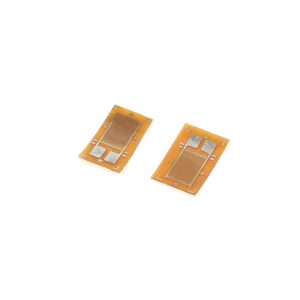
The BF350 Pressure Resistance Strain Gauge Sensor is a type of strain gauge used to measure strain (deformation) in materials. Strain gauges are widely used in mechanical engineering research and development to measure the strain on objects when a load is applied.
Features:
- Model: BF350
- Resistance: 350 ohms
- Gauge Factor: Typically around 2.0
- Sensitivity: Measures minute changes in resistance due to strain.
- Size: Compact, suitable for embedding in various materials.
Working Principle:
A strain gauge works on the principle that the electrical resistance of a conductor changes when it is stretched or compressed. The BF350 strain gauge is typically bonded to a surface, and when the surface deforms due to applied pressure or force, the strain gauge deforms as well. This deformation causes a change in the electrical resistance of the strain gauge, which can be measured and related to the amount of strain.
Applications:
- Load Cells: These are used in load cells to measure weight or force.
- Structural Testing: Used in civil engineering for testing bridges, buildings, and other structures.
- Manufacturing: Monitoring strain in manufacturing processes.
- Mechanical Testing: Used in R&D to test materials and components.
Connecting the BF350 Strain Gauge:
- Wheatstone Bridge Configuration: Strain gauges are often connected to a Wheatstone bridge configuration to measure small changes in resistance accurately.
- Amplifier: The output from the Wheatstone bridge is usually minimal and needs to be amplified using an operational amplifier or a dedicated strain gauge amplifier.
- Microcontroller: The amplified signal can then be read by a microcontroller (e.g., Arduino) for further processing.
Example Circuit:
To use the BF350 strain gauge with an Arduino, you can follow these steps:
Components Needed:
- BF350 strain gauge
- Wheatstone bridge (4 strain gauges or dummy resistors)
- Instrumentation amplifier (e.g., HX711)
- Arduino
- Power supply (typically 5V)
- Connecting wires
Steps:
- Attach the Strain Gauge: Bond the BF350 strain gauge to the surface where strain needs to be measured.
- Wheatstone Bridge Setup: Connect the strain gauge in a Wheatstone bridge configuration. If using a single strain gauge, balance the bridge with three fixed resistors.
- Amplifier Connection: Connect the Wheatstone bridge’s output to the instrumentation amplifier’s inputs.
- Microcontroller Interface: Connect the output of the amplifier to an analog input on the Arduino.
- Power Supply: Power the strain gauge, amplifier, and Arduino.
Example Code:
Here’s a basic example code to read the strain gauge signal using an Arduino:
const int analogPin = A0; // Analog pin connected to the amplifier output
void setup() {
Serial.begin(9600);
}
void loop() {
int sensorValue = analogRead(analogPin);
float voltage = sensorValue * (5.0 / 1023.0); // Convert to voltage
Serial.print(“Voltage: “);
Serial.println(voltage);
// Convert voltage to strain (this requires calibration)
// float strain = (voltage – offset) / sensitivity;
// Serial.print(“Strain: “);
// Serial.println(strain);
delay(500);
}
Calibration:
To accurately measure strain, you need to calibrate the system. This involves applying known strains to the material and recording the corresponding voltage changes to create a calibration curve.
Safety Considerations:
- Ensure the strain gauge is appropriately bonded to the surface for accurate measurements.
- Avoid excessive strain that could damage the strain gauge.
- Handle the strain gauge carefully to prevent damage to the delicate resistive elements.
Would you like more detailed information on any specific aspect of using the BF350 strain gauge, such as the Wheatstone bridge configuration or calibration techniques?