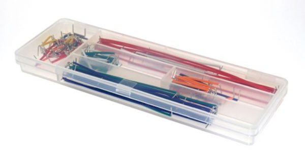


140 Pcs Solderless Breadboard Jumper Cable Wire Kit
We’re full-time makers with plenty of touch-time on the maker bench prototyping circuits. We put together a guide on breadboards and wire, which we find gets most makers up to speed, fast.
$5.99
15 in stock

This item: 140 Pcs Solderless Breadboard Jumper Cable Wire Kit
15 in stock
$5.99
$5.99

Description
Additional information
Applications
Support & Utility
Q & A
Description:
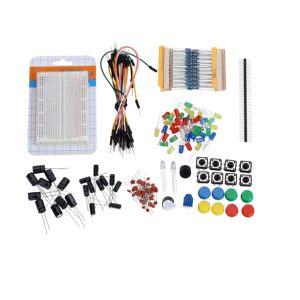
With this pack of 140 Pcs Solderless Breadboard Jumper Cable Wire Kit, you’ll create tidy circuits, stay organized and be prepared for anything when using a breadboard. This pack of breadboard jumper wire comes with 140 pieces (10 pieces of 14 lengths), pre-bent for insertion into your breadboard. The segmented case the wire comes in ensures you’ll stay organized too. We’ve found this kit to be the best option for someone starting out with electronics.
- Quantity: 140 Pcs Solderless Breadboard Jumper Cable Wire Kit makes keeping your breadboard tidy a breeze.
Features:
- -3mm
- -5mm
- -8.5mm
- -10mm
- -15mm
- -18mm
- -20mm
- -25mm
- -50mm
- -75mm
- -100mm
- -125mm
Package included: 140 Pcs Solderless Breadboard Jumper Cable Wire Kit
Check out our On Sale and Clearance Items
Development Resources: demo codes, schematics, datasheets, etc
![]() Hackaday serves up Fresh Hacks Every Day from around the Internet.
Hackaday serves up Fresh Hacks Every Day from around the Internet.
![]()
Instructables is a community for people who like to make things. Explore, share, and do your next project with us!
![]() Where the world builds software
Where the world builds software
![]() Raspberry Pi Foundation What would you like to make today?
Raspberry Pi Foundation What would you like to make today?
![]() Arduino‘s mission is to enable anyone to enhance their lives through accessible electronics and digital technologies.
Arduino‘s mission is to enable anyone to enhance their lives through accessible electronics and digital technologies.
![]()
Wikipedia is a free online encyclopedia created and edited by volunteers worldwide and hosted by the Wikimedia Foundation.
Notes:
1. There may be slight size deviations due to manual measurement, different measuring methods and tools.
2. The picture may not reflect the actual colour of the item because of different photographing light, angles and display monitors.
| Weight | 0.060 kg |
|---|---|
| Dimensions | 17 × 6 × 2 cm |
Product Applications
Invented by Ronald J Portugal for E&L Instruments and Derby CT
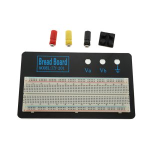
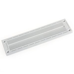
A modern solderless breadboard socket ( Invented by Ronald J Portugal for E&L Instruments and Derby CT ) consists of a perforated block of plastic with numerous tin-plated phosphor bronze or nickel silver alloys spring clips under the perforations.
Originally the word referred to a literal breadboard because of the polished piece of wood used for slicing bread.
A breadboard is a construction base for the prototyping of electronics.
In the 1970s the solderless breadboard became available.
This makes it easy to use for creating temporary prototypes and experimenting with circuit design and for this reason.
Solderless breadboards are also popular with students and in technological education.
Older breadboard types did not have this property.
Alternatives
Alternative methods to create prototypes are point-to-point construction (reminiscent of the original wooden breadboards), wire wrap, wiring pencil, and boards like the stripboard.
Complicated systems, such as modern computers comprising millions of transistors, diodes, and resistors, do not lend themselves to prototyping using breadboards, as their complex designs can be difficult to layout and debug on a breadboard.
Modern circuit designs are generally developed using a schematic capture and simulation system and tested in software simulation before the first prototype circuits are built on a printed circuit board.
Integrated circuit designs are a more extreme version of the same process: since producing prototype silicon is costly, extensive software simulations are performed before fabricating the first prototypes.
However and still prototyping techniques are still used for some applications such as RF circuits, or where software models of components are inexact or incomplete.
It is also possible to use a square grid of pairs of holes where one hole per pair connects to its row and the other connects to its column.
This same shape can be in a circle with rows and columns each spiralling opposite clockwise/counterclockwise.
Q & A
There are no questions yet
Ask a question
Your question will be answered by a store representative or other customers.
Thank you for the question!
Your question has been received and will be answered soon. Please do not submit the same question again.
Error
An error occurred when saving your question. Please report it to the website administrator. Additional information:
Add an answer
Thank you for the answer!
Your answer has been received and will be published soon. Please do not submit the same answer again.
Error
An error occurred when saving your answer. Please report it to the website administrator. Additional information: