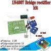
IN4007 full wave bridge rectifier Kit
This kit can be used in the practical training of primary and skill teaching of electronic technology
$3.95
6 in stock
This item: IN4007 full wave bridge rectifier Kit
6 in stock
$3.95
$3.95


Description
Additional information
Applications
Support & Utility
Q & A
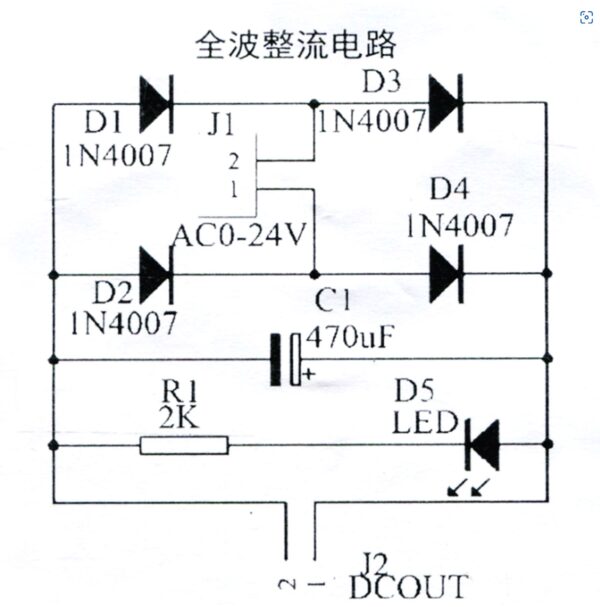
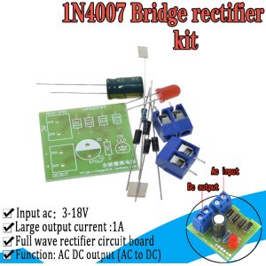
IN4007 Full Wave Bridge Rectifier DIY Kits AC DC Converter Full Wave Rectifier Circuit Board KIT Parts Electronic Suite
Specification:
- AC Input DC output (AC to DC)
- Input: 3-18 V AC
- maximum output: 1A
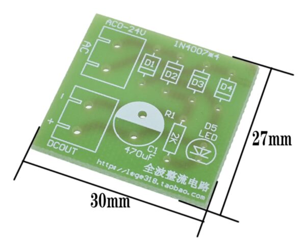
- PCB size mm [31 * 15 * 1.2]
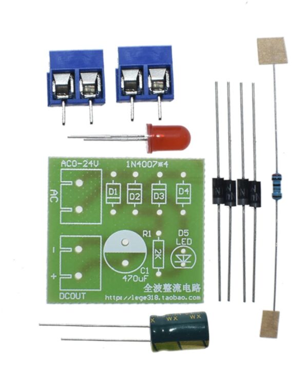
Parts Supplied :
- 4 x 1N4007 Diode 1A
- 1 x 470 uF Electrolytic Capacitor
- 1 x 2k resistor
- 1 x 5mm Red LED
- 2 x 2-way screw terminal block
- 1 x PCB
Package included: 1x IN4007 full wave bridge rectifier Kit
Check out our On Sale and Clearance Items
Development Resources: demo codes, schematics, datasheets, etc
![]() Hackaday serves up Fresh Hacks Every Day from around the Internet.
Hackaday serves up Fresh Hacks Every Day from around the Internet.
![]()
Instructables is a community for people who like to make things. Explore, share, and do your next project with us!
![]() Where the world builds software
Where the world builds software
![]() Raspberry Pi Foundation What would you like to make today?
Raspberry Pi Foundation What would you like to make today?
![]() Arduino‘s mission is to enable anyone to enhance their lives through accessible electronics and digital technologies.
Arduino‘s mission is to enable anyone to enhance their lives through accessible electronics and digital technologies.
![]()
Wikipedia is a free online encyclopedia created and edited by volunteers worldwide and hosted by the Wikimedia Foundation.
Notes:
1. There may be slight size deviations due to manual measurement, different measuring methods and tools.
2. The picture may not reflect the actual colour of the item because of different photographing light, angles and display monitors.
| Weight | 0.010 kg |
|---|---|
| Dimensions | 7 × 3 × 1 cm |
Product Applications
Scope of application:
- Used as a square wave signal generator to generate square wave signals for experimental development.
- Used to generate a square wave signal that drives the stepper motor driver.
- Generate adjustable pulses for use by the MCU.
- Generate adjustable pulses to control the associated circuitry.
Q & A
Ask a question
There are no questions yet
Related Products