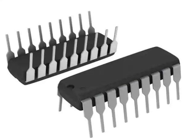
MCP23008-E/P I/O Expander 18-Pin
General-purpose, parallel I/O expansion for I2C bus or SPI applications. The two devices differ in the number of hardware address pins and the serial interface: MCP23008 – I2C interface; three address pins MCP23S08 – SPI interface; two address pins
$4.65
17 in stock

This item: MCP23008-E/P I/O Expander 18-Pin
17 in stock
$4.65
$4.65
Description
Additional information
Applications
Support & Utility
Q & A
Features:
- MCP23008-E/P I/O Expander 18-Pin
- 8-bit remote bidirectional I/O port – I/O pins default to input
- High-speed I2C™ interface (MCP23008) – 100 kHz – 400 kHz – 1.7 MHz
- High-speed SPI interface (MCP23S08) – 10 MHz
- Hardware address pins – Three for the MCP23008 to allow up to eight devices on the bus – Two for the MCP23S08 to allow up to four devices using the same chip-select
- Configurable interrupt output pin – Configurable as active-high, active-low or open-drain
- Configurable interrupt source – Interrupt-on-change from configured defaults or pin change
- Polarity Inversion register to configure the polarity of the input port data
- External reset input
- Low standby current: 1 µA (max.)
- Operating voltage: – 1.8V to 5.5V @ -40°C to +85°C I2C @ 100 kHz SPI @ 5 MHz – 2.7V to 5.5V @ -40°C to +85°C I2C @ 400 kHz SPI @ 10 MHz – 4.5V to 5.5V @ -40°C to +125°C I2C @ 1.7 kHz SPI @ 10 MHz
MCP23008-E/P I/O Expander 18-Pin, general-purpose, parallel I/O expansion for I2C bus or SPI applications.
The two devices differ in the number of hardware address pins and the serial interface: MCP23008 – I2C interface; three address pins MCP23S08 – SPI interface; two address pins The MCP23X08 consists of multiple 8-bit configuration registers for input, output and polarity selection. The system master can enable the I/Os as either inputs or outputs by writing the I/O configuration bits. The data for each input or output is kept in the corresponding Input or Output register. The polarity of the Input Port register can be inverted with the Polarity Inversion register. All registers can be read by the system master.
The way that you hook the chip up to your breadboard will depend on the package you use (8-pin MCP23008 or 16-pin MCP23017). The pinouts are quite different between the two chips, so check the datasheet carefully first.

The MCP23017 is shown above with two LEDs connected, on GPA0 and GPA1.
- The yellow line is SDA
- The green line is SCL
- The three black lines on top are the address pins
- The brown pin is RESET which must be pulled high for normal operation
- Red is 3.3V
- Black is GND.
Since these io expander chips use i2c to communicate, you can theoretically power them from 5V while still connecting the i2c data lines to a 3.3V device like the pi. That’s because the Pi has two i2c resistors that pull up SDA/SCL to 3.3V. Just make sure not to connect any resistors to SDA/SCL to 5V and you can power the chip from 5V (and have 5V input/output on the MCP chip). It’s also fine of course to power the MCP chip from 3.3V but the 5V line on the Pi has the more current capability so you might find it’s better to go that way.
BUT if your Pi power supply drifts a little higher than 5V, it might stop being able to register the 3.3V signal. So we recommend starting with 3.3V, and if you need 5V GPIO signalling on the MCP expander, try swapping the red wire to 5.0V
You can compare the two pinouts below to figure out how the 8-pin package should be hooked up depending on the pin names:


You’re free to hook anything you want up to the 8 or 16 GPIO pins, but LEDs are used here since most people have one or two lying around and it’s an easy way to verify the pin outputs. Be sure to connect a resistor in series to GND, though, to prevent the LED from burning out (if you don’t know what value or the details of your LED try something large like 1K to start with).
Here’s a quick video of the setup I was using during testing and development. An MCP23017 is used here, running out to a mixed-signal oscilloscope with an 8-channel logic analyzer (ergo the white clip-ons on all the GPIO pins).
Reference
Extra GPIO for your Raspberry Pi – Hardware setup
Other Related Products
400 Tie Point Solderless Breadboard

| Weight | 0.008 kg |
|---|---|
| Dimensions | 2 × 1.5 × 1.5 cm |
Product Applications
Current Product Support
| SKU | Product | Type | Download/View |
|---|---|---|---|
| TS-C018 | MCP23008-E/P I/O Expander 18-Pin - MCP23008 | Datasheet | Download |
Q & A
Ask a question
There are no questions yet
Related Products

MCP23S08-E/P I/O Expander 18-Pin
Price range: $4.25 through $19.50
L7812CV 12v Voltage regulator
Price range: $1.15 through $4.95
50 Pin Right Angle Boxed Header PCB Mount
Price range: $1.55 through $6.95
LD1117V33 3.3v Voltage regulator LDO
Price range: $1.75 through $7.95
Screw Terminal Block 2-Pin, 5 mm Pitch, Side Entry 5,10 and 25 Pack
Price range: $2.25 through $7.75