

Optical Automatic Switching Module Kit
This kit can be used in the practical training of primary and skill teaching of electronic technology
$7.45
6 in stock
This item: Optical Automatic Switching Module Kit
6 in stock
$7.45
$7.45

$4.95


Description
Additional information
Applications
Support & Utility
Q & A
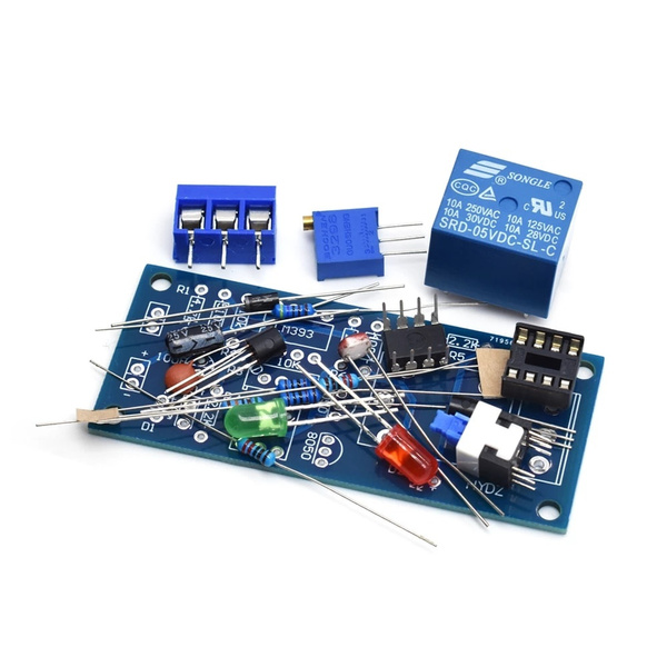
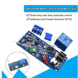
Optical Automatic Switching Module Kit Street Lamp Stair Light Automatic Control
Function introduction:
The module can be used for light inspection. Brightness detection, the detection brightness threshold can be adjusted through the potentiometer, built-in relay, can be used for various brightness detection switches, can control various street lights, automation equipment. It turns on automatically at night when there is no light (switch pressed), turns off when there is light during the day, or turns on when there is light during the day (light on pops up), and turns off automatically at night when there is no light.
This kit can be used in the practical training of primary and skill teaching of electronic technology, electronic skill teaching, electronic process teaching, digital circuit teaching, electronic enthusiasts and beginners practical training.
Feature:
1. DELAY FUNCTION: The kit delays 3 to 5 seconds; when the brightness is in a crisis state, the relay will not operate and reset frequently
2. OPTIONAL WORKING MODE: This light control switch module kit has the relay action when there is light, or the relay starts when there is no light, you can choose
3. ADJUSTMENT: The sensitivity of this switch kit can be adjusted through potentiometer adjustment and clockwise adjustment; the sensitivity is increased
4. MEET NEEDS: The DIY kit with high-quality relays that can withstand 1500W loads and meet the requirements of most people
5. BASIC SPECIFICATIONS: The working voltage is DC 5V, and the load is 250V 10A or 30V 10A DC (the current is lower than this usable range)
Specification:
- 5v relay
- Input: 5-15 V AC
- Load: 250V 10A AC or 30v 10a DC
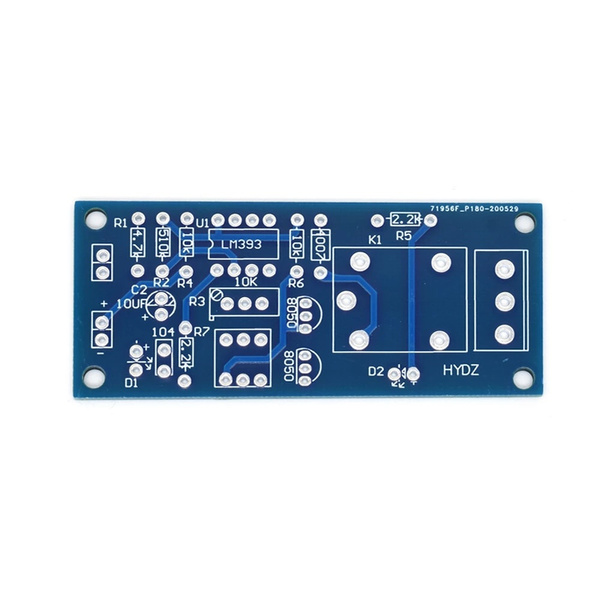
- PCB size mm 3.0 * 7.0
Parts Supplied
- LM393
- 8pin Ic Socket
- LDR
- 1N4007 Diode 1A
- 8050 x 2
- 470 uF 25v Electrolytic Capacitor
- EG1218 Switch
- 10 uF 25v Electrolytic Capacitor
- Ceramic Capacitor 104
- 3-way screw terminal block
- 10k resistor x2
- 510k resistor x2
- 2k2 resistor x2
- 1×2 Pin Header
- Trim pot x 1
- 3mm Red LED
- 3mm Green LED
- Relay
- Switch
- 4-way cable
- PCB
Package included: 1x Optical Automatic Switching Module Kit
Check out our On Sale and Clearance Items
Development Resources: demo codes, schematics, datasheets, etc
![]() Hackaday serves up Fresh Hacks Every Day from around the Internet.
Hackaday serves up Fresh Hacks Every Day from around the Internet.
![]()
Instructables is a community for people who like to make things. Explore, share, and do your next project with us!
![]() Where the world builds software
Where the world builds software
![]() Raspberry Pi Foundation What would you like to make today?
Raspberry Pi Foundation What would you like to make today?
![]() Arduino‘s mission is to enable anyone to enhance their lives through accessible electronics and digital technologies.
Arduino‘s mission is to enable anyone to enhance their lives through accessible electronics and digital technologies.
![]()
Wikipedia is a free online encyclopedia created and edited by volunteers worldwide and hosted by the Wikimedia Foundation.
Notes:
1. There may be slight size deviations due to manual measurement, different measuring methods and tools.
2. The picture may not reflect the actual colour of the item because of different photographing light, angles and display monitors.
| Weight | 0.025 kg |
|---|---|
| Dimensions | 7 × 3 × 1 cm |
Product Applications
Q & A
There are no questions yet
Ask a question
Your question will be answered by a store representative or other customers.
Thank you for the question!
Your question has been received and will be answered soon. Please do not submit the same question again.
Error
An error occurred when saving your question. Please report it to the website administrator. Additional information:
Add an answer
Thank you for the answer!
Your answer has been received and will be published soon. Please do not submit the same answer again.
Error
An error occurred when saving your answer. Please report it to the website administrator. Additional information:
Related Products


