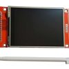
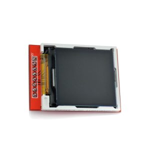
2.8-Inch SPI TFT LCD Touch SD card with Stylus
In general, it is best to operate the display off of 5V to ensure enough power is available. Be careful of trying to operate the display from the built-in 3.3V available on Arduino and similar microcontrollers since these power sources often have limited current capability and may overheat.
$24.95
3 in stock
This item: 2.8-Inch SPI TFT LCD Touch SD card with Stylus
3 in stock
$24.95
$24.95

Description
Additional information
Applications
Support & Utility
Q & A
Description:
This 2.8-inch SPI TFT LCD Touch SD card with Stylus has a 240 x 320 pixels resolution.
It uses the ILI9341 controller with an SPI interface.
It also includes a resistive touchscreen with a built-in XPT2046 controller.
These full-colour displays are large enough for many applications, even when using touch.
The supplied Stylus is helpful when using smaller touch targets.
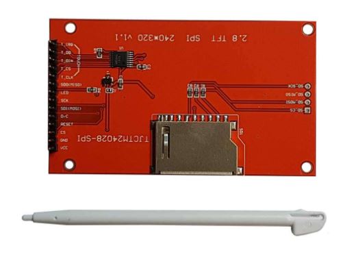
The modules have an SD card socket. This socket has separate connections to the opposite end of the board.
Internally, the display operates at 3.3V, so if using a 5V microcontroller, include logic level shifters on the data lines to prevent possible damage.
Features:
- Type: 2.8-inch SPI TFT LCD Touch SD card with Stylus
- Screen: 2.8″ SPI Serial
- SD card socket
- Driver element: a-Si TFT active matrix
- Pixel arrangement: vertical stripe
- Driver IC: ILI9341
- Backlight: White LED
- Viewing direction: 6 o’clock
- Colour depth: 262K/65K
- Resolution (dots): 240RGBx320Dots
- 5V compatible, use with 3.3V or 5V logic
- Need at least 4 IOs from your MCU
- With plate (including power supply IC, SD), compatible with 5110 interface
- Display area: 46(W) X 65(H)mm
- Size: 86 x 50 mm
Package included: 1x 2.8-inch SPI TFT LCD SD card Touch with Stylus
Check out our On Sale and Clearance Items
Development Resources: demo codes, schematics, datasheets, etc
Arduino Arduino TFT library
Module Power:
The module power comes in on the VCC pin. The module includes an onboard 3.3V regulator, so the module should normally be operated off of 3.6 to 5.5V power on this pin to feed the regulator. Current is typically 55-60mA
If you would prefer to operate the module directly from a 3.3V power source, there are two solder pads labelled J1. The regulator is bypassed by solder shorting these two pads together, and the module can be powered directly from 3.3V.
In general, operating the display off of 5V is best to ensure enough power is available. Be careful of trying to operate the display from the built-in 3.3V available on Arduino and similar microcontrollers since these power sources often have limited current capability and may overheat.
SPI Interface:
This display incorporates the SPI interface, which provides for fast display updates. It is a 4-wire interface with a CS (Chip Select).
The touch screen also uses the SPI interface and can hook to the same pins as the display. It does use a separate CS to avoid conflict.
A hardware SPI interface should be used for the best performance to get the fastest screen updates.
SD Card Socket:
The SD card socket comes out to solder pads on the opposite end of the module.
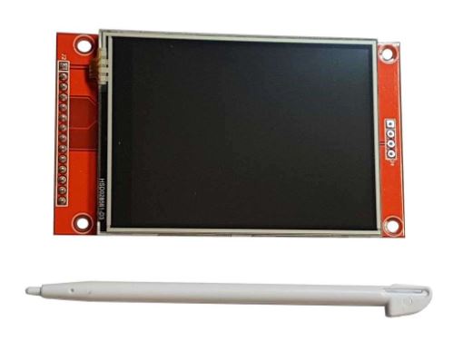
Module Connections:
1 x 14 Header
- VCC – Connect to 3.6 to 5.5V. Typically connected to the MCU, it can be a separate power supply.
- GND – Connect to system ground. This ground needs to be in common with the MCU.
- CS – Display Chip Select. This is the SPI Chip selected for the display
- RESET – Reset input active LOW. Pull to 3.3V if not using.
- DC – Data or Command. LOW = Command, HIGH = Data
- SDI(MOSI) – Display SPI Write Data. Connects to MOSI on MCU
- SCK – Display SPI Clock. Connects to SPI SCK (Clock)
- LED – LED Backlight Control. HIGH = backlight on. Connect to 3.3V if always ON or can be logically controlled.
- SDO(MISO) – Display SPI Read Data. Connect to SPI MISO on MCU
- T_CLK – Touch SPI CLock. Can connect to SCK
- T_CS –Touch Chip Select. There needs to be a separate CS from the display
- T_DIN – Touch Write Data. Connect to SPI MOSI on MCU
- T_DO – Touch Read Data. Connect to SPI MISO on MCU
- T_IRQ – Touch Interrupt Output. Active LOW. If using, connect to interrupt capable pin on MCU.
![]() Hackaday serves up Fresh Hacks Every Day from around the Internet.
Hackaday serves up Fresh Hacks Every Day from around the Internet.
![]()
Instructables is a community for people who like to make things. Explore, share, and do your next project with us!
![]() Where the world builds software
Where the world builds software
![]() Raspberry Pi Foundation: What would you like to make today?
Raspberry Pi Foundation: What would you like to make today?
![]() Arduino‘s mission is to enable anyone to enhance their lives through accessible electronics and digital technologies.
Arduino‘s mission is to enable anyone to enhance their lives through accessible electronics and digital technologies.
![]()
Wikipedia is a free online encyclopedia created and edited by volunteers worldwide and hosted by the Wikimedia Foundation.
Notes:
1. There may be slight size deviations due to manual measurement, different measuring methods and tools.
2. The picture may not reflect the actual colour of the item because of different photography lights, angles and display monitors.
| Weight | 0.100 kg |
|---|---|
| Dimensions | 9 × 6 × 2 cm |
Product Applications
Q & A
Ask a question
There are no questions yet
Related Products