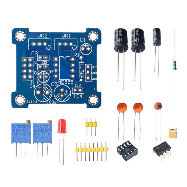
NE555 Pulse Generator Duty Cycle and Frequency Adjustable Module DIY Kit
NE555 Frequency Adjustable Pulse Generator Electronic Module DIY Kit, the adjustable pulse generator is based on NE555 chip, built into an oscillator circuit.
15 in stock

15 in stock


Description:
- Output has LED indication, and the output is directly clear (LED on when the level is low, LED off when the level is high, and LED flashing when the frequency is low);
- Frequency output range is optional (selected with a short-circuit cap) to make the output frequency more continuously adjustable;
- Duty cycle output can be fine-tuned, while duty cycle and frequency are not adjustable separately, adjusting the duty cycle will change the frequency;
- The output frequency is adjustable.
Features:
- Operating Temperature: -30~85 Celsius
- Model Number: NE555 Pulse Starter:
- 5-15V DC (when 5V is supplied, the output current can be around 15mA
- 12V is supplied, the output current can be around 35mA)
- Input current: ≥100mA
- Output amplitude: 4.2V V-PP to 11.4V V-PP (the output amplitude will be different depending on the input voltage)
- Maximum output current: ≥15mA (5V power supply, V-PP is greater than 50%), ≥35MA (12V power supply, V-PP is greater than 50%)
Package included: 1x NE555 Pulse Generator Duty Cycle and Frequency Adjustable Module DIY Kit
Check out our On Sale and Clearance Items
Development Resources: demo codes, schematics, datasheets, etc
Output Frequency Range
-
LF File: 1 Hz – 50 Hz
-
IF File: 50 Hz – 1 kHz
-
High-Frequency File: 1 kHz – 10 kHz
-
HF File: 10 kHz – 200 kHz
Adjustable output frequency
- Period T = 0.7 (RA +2 RB) C
- RA, RB 0-10K adjustable
- Low Profile When C = 0.001UF
- IF Stalls C = 0.1UF
- High-Frequency File C = 1UF
- HF Stalls C = 100UF
- Supply Voltage: DC5-12V
- Type: Logic ICs

![]() Hackaday serves up Fresh Hacks Every Day from around the Internet.
Hackaday serves up Fresh Hacks Every Day from around the Internet.
![]()
Instructables is a community for people who like to make things. Explore, share, and do your next project with us!
![]() Where the world builds software
Where the world builds software
![]() Raspberry Pi Foundation What would you like to make today?
Raspberry Pi Foundation What would you like to make today?
![]() Arduino‘s mission is to enable anyone to enhance their lives through accessible electronics and digital technologies.
Arduino‘s mission is to enable anyone to enhance their lives through accessible electronics and digital technologies.
![]()
Wikipedia is a free online encyclopedia created and edited by volunteers worldwide and hosted by the Wikimedia Foundation.
Notes:
1. There may be slight size deviations due to manual measurement, different measuring methods and tools.
2. The picture may not reflect the actual colour of the item because of different photographing light, angles and display monitors.
| Weight | 0.010 kg |
|---|---|
| Dimensions | 7 × 3 × .5 cm |
Product Applications
Scope of application:
- Used as a square wave signal generator to generate square wave signals for experimental development.
- Used to generate a square wave signal that drives the stepper motor driver.
- Generate adjustable pulses for use by the MCU.
- Generate adjustable pulses to control the associated circuitry.
Q & A
Ask a question
Your question will be answered by a store representative or other customers.
Thank you for the question!
Your question has been received and will be answered soon. Please do not submit the same question again.
Error
An error occurred when saving your question. Please report it to the website administrator. Additional information:
Add an answer
Thank you for the answer!
Your answer has been received and will be published soon. Please do not submit the same answer again.
Error
An error occurred when saving your answer. Please report it to the website administrator. Additional information: