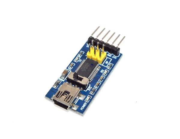
FT232RL USB To TTL USB to TTL Program
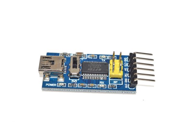
The board has a jumper that allows you to select between supplying 5V or 3.3V to this VCC pin. When operating at 5V, the full USB maximum current of around 500 mA is available.
$6.95
5 in stock
This item: FT232RL USB To TTL USB to TTL Program
5 in stock
$6.95
$6.95

Description
Additional information
Applications
Support & Utility
Q & A
Description:
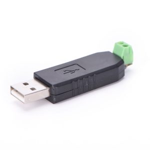
The power for this FT232RL USB To TTL USB to TTL Program comes from the USB port.
Features:
- Support 3.3V, 5V
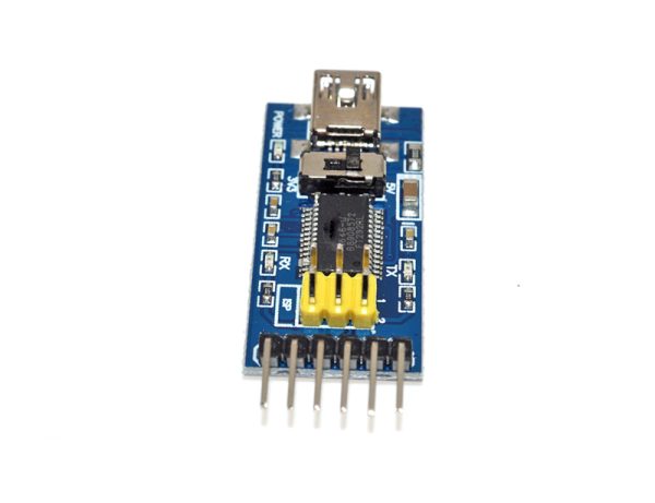
- Chipset FT232RL
- Machine PLC data reading and writing
- Monitoring data read and write, and PTZ control
- LED display of communication data
- USB power has over current protection, using 500MA self-restore fuse
- RXD / TXD transceiver communication indicator
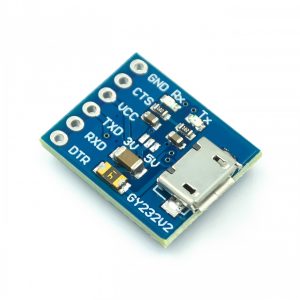
- Pin definition: DTR, RXD, TX, VCC, CTS, GND
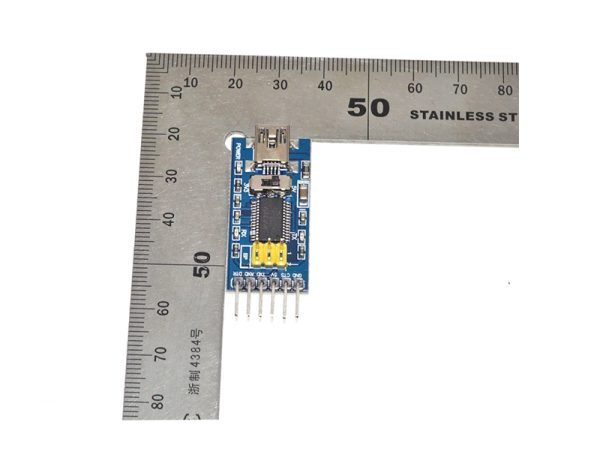
- Pitch: 2.54mm
Package included: 1x FT232RL USB To TTL USB to TTL Program
Check out our On Sale and Clearance Items
Development Resources: demo codes, schematics, datasheets, etc
Power
That USB power is also made available on the header VCC pin to power up the board that the module is plugged into if needed.
If operating at 3.3V, this power comes from a regulator built into the FT232RL chip and the output is limited to only 50mA.
Module Connections
The module uses a Mini-B style USB connector for connection to the PC.
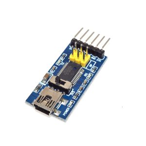
The Serial TTL interface is brought out to a right-angle header.
In addition to the header, the I/O from those pins, along with additional I/O from the pins of the FT232RL chip, are brought out to breakout points along the edge of the board. These normally aren’t needed but do provide easy access points to support atypical applications. The breakout points also allow straight headers to be soldered in so that the module can be mounted flat on a breadboard if desired.
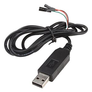
Hookup is straightforward. The USB end plugs into your computer USB port using a standard USB to mini-B USB cable.
Most applications will just use the RX and TX pins cross-connected between the FT232RL module and your device that you are trying to control on the TTL side. RX on module goes to TX on the device, and TX on module goes to RX on the device. There are transmit and receive LEDs on the module that shows activity on these lines. You will also need to connect the GND pin to the ground on the device.
![]() Hackaday serves up Fresh Hacks Every Day from around the Internet.
Hackaday serves up Fresh Hacks Every Day from around the Internet.
![]()
Instructables is a community for people who like to make things. Explore, share, and do your next project with us!
![]() Where the world builds software
Where the world builds software
![]() Raspberry Pi Foundation What would you like to make today?
Raspberry Pi Foundation What would you like to make today?
![]() Arduino‘s mission is to enable anyone to enhance their lives through accessible electronics and digital technologies.
Arduino‘s mission is to enable anyone to enhance their lives through accessible electronics and digital technologies.
![]()
Wikipedia is a free online encyclopedia created and edited by volunteers worldwide and hosted by the Wikimedia Foundation.
Notes:
1. There may be slight size deviations due to manual measurement, different measuring methods and tools.
2. The picture may not reflect the actual colour of the item because of different photographing light, angles and display monitors.
| Weight | 0.008 kg |
|---|---|
| Dimensions | 6 × 2 × 1.5 cm |
Product Applications
Works for Centralized control of household electrical appliances, Access Control System, A variety of industrial automation, instrumentation Parking, bus fees, Dining Hall, staff attendance, Highway toll station and ATM machine.
Q & A
Ask a question
There are no questions yet